Smartpen with 128×64 RGB POV display
This post describes a Smartpen with a 128×64 RGB POV display embedded into the pen’s clip.
—
Sometimes while sitting in a meeting, I see some people staring for 30s or more onto their watch. To me this always looks a bit like a first grader that is learning how to read the clock. So you can guess by now that I am not a big fan of Smartwatches.
But still, the ability to check for messages without looking at your Smartphone seems to be desirable, especially while sitting in a meeting.
This motivated me to think of alternatives to the Smartwatch. Of course, it should be an everyday object that is improved by some “smartness”. Thinking again of the meeting situation, the only other typical object I could think of would be a pen.
Of course, the surface of a pen is a bit too small to add a high resolution display to it. And in addition, this would be quite boring. Therefore, I wanted to add a high resolution POV display by embedding a line of LEDs into the clip of the pen.
Sometimes, I just wiggle normal pens between my fingers. With the addition of the LED line in the clip I would then be able to display a high resolution image. And that is my idea of a Smartpen.
Here you can see a prototype of my Smartpen:
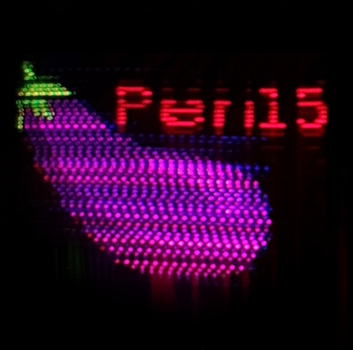
The pen contains 192 LEDs that form a line of 64 RGB dots in the clip of the pen. This creates a display with a density of 101 PPI, which is extremely high for a POV display. In fact, during my research I have never seen a POV display with a similar pixel density. The highest I found had 40 PPI monochrome. The following picture shows an image that is displayed by the pen (real world size: 20x20mm):
This display together with a Bluetooth module that connects to your Smartphone would then create the Smartpen that could show you new messages, emails, etc.
As you can imagine, embedding almost 200 LEDs that are individually addressable into a pen as well as a pixel density of 101 PPI is quite challenging. This post will describe how I addressed these challenges.
Please note that my Smartpen is more a proof-of-concept than a usable device. Several issues together with a lack of time had stopped me from finishing the project. At the end of this post I will explain in more detail these issues.
LEDs
I explored many options for the type of LEDs in this project. It was quite clear from the beginning that 200 discrete LEDs are not an option due to limited space. Also, the standard “smart LED” WS2812 with its 5x5mm footprint is way too big for this project. In addition to that, the chip of the WS2812 uses a single-wire protocol that is more complicated to use than SPI and is also much slower to update. Update speed is quite crucial in this project. With an image width of 128px and an update rate of 15fps, each LED would need to be updated at a rate of 2kHz.
After a bit of searching I was quite happy to find the APA102-2020. This RGB LED comes in a tiny 2x2mm package and has a normal SPI bus. So it was perfect for my application. That’s why I’ve bought a couple of hundreds of them.
But… when they arrived I noticed something odd. They worked as expected but there was one tiny thing that was not according to the datasheet: The PWM frequency of the LEDs. Being not like the 20kHz mentioned in the datasheet it was more in the lower kHz region. The following image shows this problem. In that picture, I did set the green LED to half intensity (constantly on) and moved it quickly:
As you can see, the LED shows a dotted line instead of a solid one. And the dot pattern is exactly the PWM pattern. This is of course very annoying because if would mean that the display will have this dot pattern for all color values that are not 0xff.
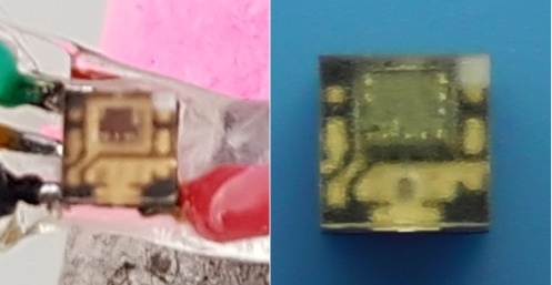
After a bit of research I found that the manufacturer of the LEDs has at some point replaced the driver chip inside of the LED. The old one has the fantastic 20kHz PWM, the new one has the shitty PWM. It is quite easy to find out which one of the drivers the LEDs have: The older driver chips are larger. You can see this on the following picture (left: new, right: old):
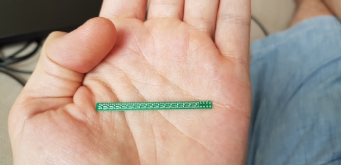
Since I already bought hundreds of LEDs I continued the project nonetheless: I designed a small PCB that daisy-chains 16 of these LEDs:
The PCBs can be daisy-chained as well:
One of these LED stripes already showed its suitability as a POV display:
In the “hearts” image you can see a typical problem of POV displays: The spacing between the individual dots due to the spacing of the individual LEDs. Because of that, POV displays have typically this “lineish” appearance – not very pretty. The next section describes how I fixed this.
The clip of the pen
So, how can you fit 64 LEDs of size 2mm into the clip of a pen that is only 30mm long? And how do you avoid this “lineish” appearance of POV displays? The answer is simple: Fiber optics!
Fiber optics take the light of the LEDs and route it through the pen to the clip. On the clip, each of the tiny 250um fiber optics is one dot of the display.
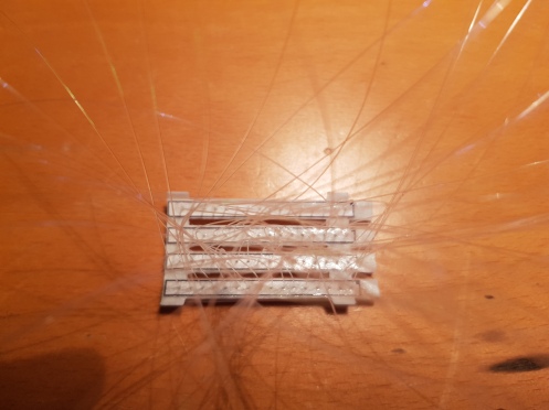
First, I 3D-printed with flexible filament a holder for four LED PCBs:
The paper stripes on the left are templates that I glued onto the 3D print. After that I used a needle to punch a hole into the 3D printed part for each fiber. Then it was very easy to put a fiber through the hole and glue it onto the 3D part:
This assembly can be rolled together and the fibers then exit through the clip of the pen:
If you look closely at the picture above, you can see the fibers in the center of the clip glowing.
The following video shows the display unit in action:
If you look closely you can see that the LEDs and the fibers on the clip are not in the same order. I tried several times to align the fibers in the right order at the clip but I always failed. Since you have to move the fibers very close together they have a tendency of jumping over other fibers and screwing up the order. Therefore I just glued them in, ignoring the order and sorted things out by reordering them in software.
Display unit + IMU + Raspi
The last bit needed to use the display unit as a POV display is a way to determine the position of the clip. For this purpose, I used a MPU6050 IMU. You can see the IMU on a breakout board glued onto the pen in the first picture of this post. Actually, the 6 axis IMU is a bit overkill. For the display application I only used one axis of the gyroscope. While wiggling the pen between your fingers you can easily detect the turning points by looking at high angular accelerations.
All the software needs to do is to start displaying the image column by column when it detected the left turning point. Upon the detection of the right turning point the image is displayed in reverse order, again column by column.
I implemented the software on a Raspi since this allows for much faster development compared to a microcontroller. All you need to do is to connect the IMU to the I2C bus and the display unit to the SPI bus of the Raspi.
I created the images to display on the pen using Gimp and exported them as C header (yes, Gimp can do this directly, a very handy feature!).
As usual, you can find the source code, the Kicad files and the SCAD files for the mechanics in a Bitbucket repository:
git clone https://bitbucket.org/befi/pen15
Please note that the repository contains a later version of the mechanics compared to the pictures of this post. In the new version, the LED PCB holders are split into two parts (one holding the PCB, one holding the fibers) that are to be glued together. The motivation for this was to be able to polish the fibers after gluing them in for having a more consistent brightness between individual fibers.
Open issues
LED PWM frequency
Like mentioned above, the PWM frequency of the APA102-2020 is too low for this application. You can see this especially on the eggplant image above. The body of the original eggplant is filled with a solid color. Since this color is different from 0xff, we get this strange dotted pattern – not very nice.
(Side note to the image: There is a dead fiber at the top of the font. It broke during some reworks on the mechanics)
There are basically only two ways around this: Either limit yourself to 8 colors (using either 0x00 or 0xff per channel) or use different LEDs. Like mentioned before, there are (most likely earlier) variants of the APA102-2020 that do not have this PWM issue. However, I was unable to obtain them. I ordered my LEDs from Digikey and Adafruit and received always the flawed LEDs.
Crosstalk
Crosstalk happens because the light of a LED is forwarded by one of its neighbor fibers. You can see the effect also in the eggplant image, especially at the font. The “shadow” effect seen at the bottom comes from crosstalk.
Working around this issue should not be too hard. In fact, the hardware files that are in the latest revision of the projects repository should already help a lot. Instead of white flexible filament they use normal black PLA. This should remove much of the crosstalk created by translucence and reflectivity of white PLA.
Inconsistent brightness
Keeping the brightness constant between the fibers is quite tricky. You can see the effect in the font of the eggplant image. Some lines are brighter than others. For getting the brightness right, the placement (in all 3 axes) relative to the LED as well as the orientation of two of the angles of the fiber needs to quite good. Also, the end of the fiber needs to be polished so that you get equal light transmission. I think (especially with the latest hardware revision that allows to polish the fibers after they are glued in) this issue is solvable… but tedious.
Heat
Do not underestimate the heat that is generated by 200 LEDs! I learned this the hard way. Appareantly, the LEDs do not have a proper reset circuit. So when they are powered on, the LEDs show random values. I once turned the system on without starting the software (that resets them) and left it running for a couple of minutes. The result was that by 3D printed parts were molten.
I think if you take care that the LEDs are not constantly on, the heat generation is manageable. But better add a watchdog for a final usage 🙂
Future extensions
Bluetooth
Obviously, a Smartpen without any way of communication wouldn’t be that smart. It could maybe show the time but that would be it. Therefore, my plan was to use a Bluetooth Low Energy SOC like the Nordic nRF51822. Using BLE could allow the pen to stay paired with a smartphone for years on a single battery.
Handwriting recognition from IMU data
A nice addition of the Smartpen would be a way to add interaction. Simple interaction might be realized by using the IMU to send basic commands. However, more complex interactions might need more powerful approaches.
One thing I would be curious to try out would be the addition of a pressure sensor (pressure of pen onto paper). I could imagine that by combining pressure readings together with IMU readings one could realize a rudimentary handwriting recognition. It would indeed be a good task to throw some Tensorflow magic at 🙂
Interaction using handwriting recognition
Once you are able to recognize written characters, you could use that power also as a way for interaction. You could use for example arrows to navigate through menues.
Summary
The intention behind this post was to share my idea of a Smartpen and communicate my approach to it, including the difficulties I faced. Like I said before, there is still a lot of work to be done until it is a useful device. I hope very much that someone will pick up the project from here on. In case you have any additional questions, please drop a comment here and I will try to answer them.


Trackbacks & Pingbacks