Enable 2.4GHz RC systems to work with 2.4GHz video systems
This post shows how to modify most 2.4GHz RC systems so that they won’t interfere anymore with 2.4GHz video transmission systems.
—
Introduction
Ever since the 90s I used my good old Graupner MC15 35MHz system. This worked always well, also with my first quadcopter “Mikrokopter”. But when I changed to my Naze32 system the RC started to become unreliable. This has led to at least three crashes which was quite annoying. Even with lots of ferrites and other filtering elements I could not get the system to work reliable anymore.
So it was time to look for alternatives. But… my video transmission based on wifibroadcast used 2.4Ghz technique. It is well known that 2.4GHz RC systems interfere with WIFI and and analog transmission.
One idea to overcome this issue was to trim the frequency of the TL-WN722N card below 2.4GHz. Here are the required changes to the kernel described. However, this approach has several disadvantages. First, the WIFI cards most likely do not have any calibration data if you leave the official channels. I tested my cards in my microwave oven and noticed a much higher packet loss rate. In fact is was so high that a wifibroadcast video transmission would not be possible. The second disadvantage is that this is illegal to use outside of a shielded cage. In summary: Not an option.
The second possibility would be to buy a 2.4GHz RC system and switch to 5GHz wifi equipment for wifibroadcast. The problem here is that I did not want to buy new wifi sticks. I developed everything for the TL-WN722N and I really like them. In the past I had to test a bunch of other cards until I found the TL-WN722N… Plus since they use 2.4GHz they offer a more robust transmission in case of obstacles. So again, not an option for me.
Mh, and now? There are DIY FrSky modules available. Refer to this nice project. This could have been used with an altered frequency scheme so that not the whole 2.4GHz band is used. But… RC is the most critical part of a quadcopter. And I am not really in the mood to do experiments on this part. It’s quite some work to get the RX and TX modules to run and then I don’t know anything about the reliability of the code or the range and quality of the TX modules… The answer is the same: Not an option.
But I liked the idea of using a 2.4GHz RC system that does not use the full spectrum. I looked around and found no systems that lets the user configure the spectrum. But what if we could modify a bought system in that respect? This is what this post is about.
How most 2.4GHz RC system are working
Most of the RC systems (Hott, Frsky, Hitec, …) use the TI CC2500 chip for the RF communication. The chip is used in a hopping scheme so that a narrow-band channel changes its frequency over the entire 2.4GHz spectrum at a high frequency (100 times per second in case of Hott). This is the trick why these RCs are so robust. Even if there are disturbances on some channels the chances are high that still packets on other channels come through.
The CC2500 is connected to a microcontroller via SPI and transmits or receives data under control of the microcontroller. This is the case for the transmitter as well as for the receiver.
If you take a look at the CC2500s data sheet then you’ll find that this chip has a channel register. This is what’s used to implement the frequency hopping. Both microcontrollers on TX and RX write the same channel sequence into this register so they hop “together” through the spectrum.
So all there is to do is to change the sequence they use and limit its values.
Ways to modify the channel register data
The most obvious way would be to change the software on the microcontroller in the RX and TX so that only a portion of channels is used. Unfortunately, firmware updates (in case of Hott) are encrypted. So one would need to find the encryption algorithm, possibly the key and need to reverse engineer the firmware. Things get even worse because you would have to do this twice, both for RX and TX. And again for every new firmware version. And again for other models. And again for other manufacturers. What a nightmare.
Another approach would be to alter the hardware. One would need to build a device that monitors the SPI communication between the microcontroller and CC2500 and modify the writes to the channel register. While this is a bit less elegant that a software-only solution it provides one major advantage: It works for all CC2500 based systems. Regardless of the firmware version, model, manufacturer… it always works. That’s why I’ve chosen to go down that road.
SPI injector
As said above, the SPI injector should watch for SPI writes to the channel register and overwrite its value. I’ve choosen to always set the MSB of the channel value to zero. This way the spectrum is always in the lower half of 2.4GHz.
I’ve chosen a CPLD to do the work. The reason is that it would be quite tough to get the timing right with just a microcontroller. The SPI bus runs at 4MHz so a microcontroller that just runs two or three times faster might not be able to change just a single bit at the right time.
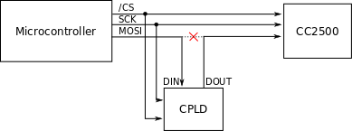
This schematic explains nicely how the CPLD integrated into the system:
Here you can see that the CPLD listens on the SPI lines. However, the original connection of the MOSI signal has been cutted and is feeded through the CPLD. Whenever the channel register is written, the CPLD zeros the MOSI signal at the right time.
This is also visible in the waveforms:

The red arrow shows the position where the CPLD has overwritten one bit (DIN is original data, DOUT is modified data).
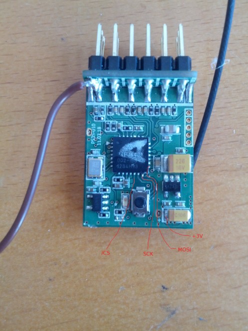
I modified a Graupner GR-12 receiver. You can see the connections on the PIC microcontroller here:
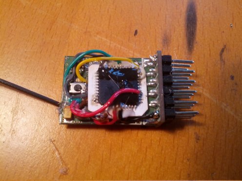
Here is a picture of the modified receiver:
If you want to apply this hack to a different receiver, you just need to follow the traces from the CC2500. Of course, you need to patch both the receiver and the transmitter (so that both agree on the channels they choose).
Checking if things work well
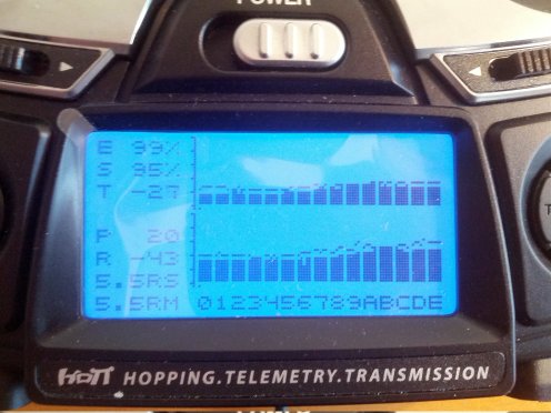
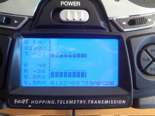
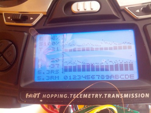
I needed a way to check if my changes did work and affected the spectrum. Luckily my TX (Graupner MZ-12) provides a view on which channels it received data.
Here you see the default (unmodified system) output where all channels are more or less available:
When I integrated the SPI injector only on the receiver side, half of the channels (the upper channels) should be deactivated. The reason for this that now the TX and RX disagree on the upper half of the channels. TX still uses the original hopping scheme while RX uses the modified scheme. The TX spectrum agrees 🙂
After both devices have been modified the spectrum looks ok again (because now both devices agree on the hopping scheme):
Notice the symmetry? This is because the upper half of the channels is now remapped by the CPLD to the lower half. So it is to be expected that the spectrum diagram tells more or less the same for both halves.
How to rebuild
First, you need to clone the repository:
hg clone https://bitbucket.org/befi/cc2500_rc_freq_mod
In the repository you find the sources as well as a testbench for simulation, an UCF file for defining the pinout and prebuilt images.
Second, you need to buy two Xilinx XC9536XL CPLDs. These costs only around 2€ pp.
As a next step you need to flash a XC9536XL CPLD from Xilinx with the prebuilt files. There are many ways to do so. You could use the official Xilinx JTAG cable, a parallel port adapter, a bus pirate and many more. You find lots of information in this Hackaday howto.
The last step is to find out the traces on your TX and RX, cut the MOSI trace and wire up the CPLD. The pinout is described in the spi_mod.ucf file.
Conclusion
In this post I presented a cheap way to modify the spectrum of a RC system. One advantage is that only the channel scheme is modified. Since all other aspects of the RC system are untouched, you still have the good range and high reliability of the original system.
Most importantly, this modification works on all RC systems that use the CC2500 chip, irregardless of brand, model or firmware version.
Great work! This is a little more hardware hacking than I was hoping for but apart from that exactly what I was looking for. Thanks! 😉
@befinitiv Why not implement two way communication, surely you can do wifibroadcast but working both ways just use a different channel. This would allow you to control the aircraft! You would have to have a low throughput pipe which is lossless though for control? Should be able to get super low latencies with just RC.
I really want you to get yourself Arducopter. Have you heard of the Navio+?
It is a Raspberry Pi cape which has all the sensors required for an autopilot. They even have the Arducopter code working for it. It would be great to integrate wifibroadcast with it, you’d simply have to run it on the raspberry pi which the Navio is on. But you could just fetch the telemetry on the board. If you’re going to start coding say, an OSD then MAVlink is probably the best way to go since it’s the standard.
Thanks!
Hi
Yes, two-way communication would also be an approach. However, when it comes to RC I am quite conservative. The hopping scheme of 2.4GHz RCs is quite robust. In fact it should be a lot more robust than using a single-frequency wifi connection. And in my opinion RC is more important than video. In case you are loosing video you could still react (gain height, enable position hold, go down) whereas if you loose RC (or potentially both RC and video since they use the same mechanism) you are lost.
@hqdby I’m already running wifibroadcast on my hexa PI and NAVIO with a soft OSD, doing test right now but is working pretty good so far.
Another thought: I would have to modify all my receivers and was looking for an alternative. FrSky offers alternative firmware that implements changes required by ETSI EN 300 328 V1.8.1 for EU transmitters. Before transmitting, available channels are checked for interference… anybody here that uses EU receivers after 01/2015 or updated their firmware? Any improvements in regards to interference?
Interesting. If the new regulation does not help you also could make this hack even hackier. Two possible options:
– Even if you only patch your TX it should still work with unpatched RXs. You loose however half of the channels which should result in a reduced update rate (assume each second channel is lost then your update rate would drop to half).
– If you need this hack only for a certain RX you could add a two-way switch into the MOSI line on the TX to switch between normal mode and half-spectrum mode.
My last crash set be back a few days, the whole platform is crushed. 😦
I think I’ll go for the bypass switch on TX and update only the relevant RX. You don’t happen to have some CPLDs lying around or would be willing to flash some for a little compensation? I’m not really using CPLDs anywhere and would need to buy the equipment for flashing…
Sorry to hear about your crash 😐
I am afraid that I cannot program the devices for you. But you can buy the chips at every corner:
http://www.reichelt.de/XC-9536XL-VQ44/3/index.html?&ACTION=3&LA=446&ARTICLE=40157&artnr=XC+9536XL+VQ44&SEARCH=xc9536xl
http://www.digikey.de/product-detail/de/XC9536XL-10VQG44C/122-1385-ND/826988
…
Programming them is also very easy. There are countless ways to do so (with very cheap equipment). For example, an Arduino is sufficient: https://github.com/sowbug/JTAGWhisperer
Just look for anything that can replay XSVF files. Hope this helps!
OK, now that my y6 is repaired I’m back to this 😉
Thanks for the useful tipps, I was looking for programmers but your tip is definitely the way to go for me.
@ronerto That’s interesting! Are you doing the osd on the receiver end? It would be nice to see some pictures.
@hqdby1 I’m using standard telemetry on the radio side just battery volts, signal and gps, for the osd im using it for fpv with a HEADPLAY unit and all data from Navio sensors, its been develop by a Emlid community member. right now i’m thinking on using some other frequency cos my RC Radio is new and I’m better with Hardware than software but it’s need to be another option, i’m researching on Ubiquiti systems but maybe a better approach will be for simple 5ghz simple usb dongle.
I am wondering why do you need to change anything at all? If you are transmitting on one channel it will jam only one RC receiver channel, that is actually how it should withstand wi-fi interference in the first place. So losing 10ms of commands in a worst case should not be a problem at all, especially since you can not really do aerobatics with 100+ ms video lag. As for video receiver it should be 1/2.5 -1/3 of one frame duration interference, that is where our FEC should come into play right?
and by making that video tx channel to be 1st or 13th, we can reduce crosstalk to other channels twofold.
hey there befinitiv,
first of all thank you so much for sharing the effort you’ve invested in this great FPV solution and the RC radio mod.
after a first look this at this modification I decided to go for a 5ghz solution because I am lazy x). Unfortunately I could not find any 5ghz wifi dongle suitable for wifibroadcast.
Alfa AWUS051NH seems to use the rp-sma jack only for 2,4ghz operation.
“A/N(5) operates via internal printed board. Do not expect proper results using 5ghz Yagi antenna with this product since you can’t access the 5ghz input via the RP-SMA jack!!!”
(according to this post: https://forums.hak5.org/index.php?/topic/32347-recommend-wifi-adapters-working-with-kali/page-2#entry245964)
This would explain the reception issues other users are facing with this wifi dongle while using 5ghz.
In my opinion the signal would be way too weak for any fpv application without an external rp-sma antenna.
I went ahead and checked my RC receiver, but it is using a CC2533 chip instead of CC2500.
Do you think your modification could also work with the CC2533 chip?
greetings cephyr
Hi
concerning the CC2533: You would have to take a look at the datasheet if the channel register is written the same way as with the CC2500. If yes then the chances are good that it will work!
Deuter is the brand that showed me how lacking my Camelbak was, which was leaky, sweaty, and cumbersome with how it distributed its weight and could flop around..One feature the guy missed is how the pack is profiled to duck under branches and stuff easier, without worry of snagging.
Hello Befinitiv
Nice hack 🙂 , Do you think it might be feasible with a stock Turnigy TGY9X?
It is using the A7105 chip.
Here is the Sequence taken from my receiver when sniffing out the SPI data:
–preamble: 64 24 69 85 37 55 81 0
— 8 Channel pair
115 5
9 6
218 3
194 5
101 4
218 5
218 5
101 4
–freq Hopping (always ending with 7)
15 157
sometimes we get a hopping sequence interleaved
15 77
So if I get it right, It would be a matter of changing “05” for “15” in the code ?
overwrite_enable_re <= '0';
if sr_cnt = 7 then
if sr(6 downto 0) = x"05" and DIN = '0' then
overwrite_enable_re <= '1';
end if;
if sr(6 downto 0) = "0111111" and DIN = '1' then
burst_disable <= '1';
end if;
end if;
Why not just use 2.3ghz wifi transmission 🙂 A few of the standard cards can do it http://yo3iiu.ro/blog/?p=1301
you could even build this into your raspi kernels so that the user doesn’t have to do anything
Yes, there are patches around for changing the frequency. But the ready-to-use images that I published are always “legal” images where I haven’t done the nasty things. However, I’ve published all software for everybody to reproduce the images. Adding the 2.3GHz patches there is very simple.
Personally, I hacked my radio to avoid transmitting into a band where I am not allowed to transmit. But most people are not such a coward like me 🙂